Skip to product information
1 of 1

Blue PCB Electronics

2A12 16 Channel 12-bit PWM/Servo Driver-I2C interface PCA9685 module

2A12 16 Channel 12-bit PWM/Servo Driver-I2C interface PCA9685 module

Regular price Dhs. 30.00
Regular price Dhs. 35.00 Sale price Dhs. 30.00
Sale Sold out
View full details

Description:

This module is a breakout board for the NXP PCA9685 16 channel PWM controller. It features 16 fully programmable PWM outputs with a 12bit resolution giving a total of 4096 programmable steps with a duty cycle being adjustable from 0% to 100%. Additionally, the output frequency of all 16 channels can be programmed from 24Hz to 1526Hz.

Intended for controlling the brightness of multiple LEDs, the programmability of its PWM outputs means that it can also be configured for producing PWM signals compatible with driving standard servos.

In fact, this module has been designed with this purpose in mind with 16 sets of headers that allow for any servo with a standard header to be directly plugged into the module. A screw terminal block provides a means of powering the attached servos from an external 5V PSU and so the number of servos you can drive from your microcontroller and so is not limited by the microcontrollers own power supply.

The module also includes an I2C header with 10K pullup resistors and so only requires two data pins (SDA & SCL) to control the module. Solderable pads on the module provide a means of changing the default I2C address (0x40) to one of 62 options, meaning more than one module can be connected to the same I2C bus. 

A wide operating range of 2.3V to 5.5V allows the module to be powered from a range of power supplies and when powered from a 3.3V supply is safe to interface to a Raspberry Pi or 3.3V or any other non 5V tolerant microcontrollers. 

NOTES

The PWM output pins on this module are capable of sinking a maximum of 25mA or sourcing a maximum of 10mA. Do not attempt to drive high current devices such as motors, bulbs etc, directly from these pins as you will risk damaging the module. For servos, power is provided externally via the terminal header and only a small amount of current is drawn by the servo from each PWM pin.


Specifications

  • Driver Type:  Servo
  • Max. Current per Channel:  0.25A
  • Frequency: 40-1000Hz
  • Channel number: 16 channel
  • Resolution: 12 bit
  • Voltage: DC 5-10V

Features

  • It's an i2c-controlled PWM driver with a built in clock. That means that, unlike the TLC5940 family, you do not need to continuously send it signal tying up your microcontroller, its completely free running!
  • It is 5V compliant, which means you can control it from a 3.3V microcontroller and still safely drive up to 6V outputs (this is good for when you want to control white or blue LEDs with 3.4+ forward voltages)
  • 6 address-select pins so you can wire up to 62 of these on a single i2c bus, a total of 992 outputs. That's a lot of servos or LEDs
  • Adjustable frequency PWM up to about 1.6 KHz
  • 12-bit resolution for each output - for servos, that means about 4us resolution at 60Hz update rate
  • Configurable push-pull or open-drain output
  • Output enable pin to quickly disable all the outputs
  • Terminal block for power input (or you can use the 0.1" breakouts on the side)
  • Reverse polarity protection on the terminal block input
  • Green power-good LED
  • 3 pin connectors in groups of 4 so you can plug in 16 servos at once (Servo plugs are slightly wider than 0.1" so you can only stack 4 next to each other on 0.1" header
  • "Chain-able" design
  • A spot to place a big capacitor on the V+ line (in case you need it)
  • 220 ohm series resistors on all the output lines to protect them, and to make driving LEDs trivial
  • Solder jumpers for the 6 address select pins
adafruit_products_815-06.jpg

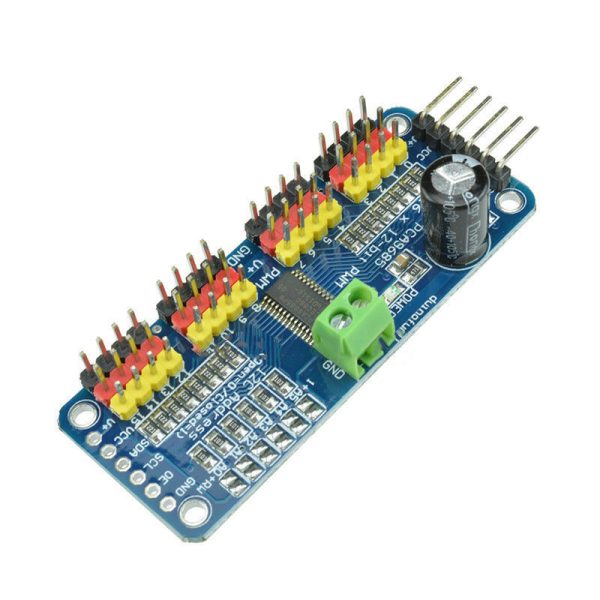
There are two sets of control input pins on either side. Both sides of the pins are identical! Use whichever side you like, you can also easily chain by connecting up two side-by-side


Power Pins

  • GND - This is the power and signal ground pin, must be connected
  • VCC - This is the logic power pin, connect this to the logic level you want to use for the PCA9685 output, should be 3 - 5V max! It's also used for the 10K pullups on SCL/SDA so unless you have your own pullups, have it match the microcontroller's logic level too!
  • V+ - This is an optional power pin that will supply distributed power to the servos. If you are not using for servos you can leave disconnected. It is not used at all by the chip. You can also inject power from the 2-pin terminal block at the top of the board. You should provide 5-6VDC if you are using servos. If you have to, you can go higher to 12VDC, but if you mess up and connect VCC to V+ you could damage your board!

Control Pins

  • SCL - I2C clock pin, connect to your microcontrollers I2C clock line. Can use 3V or 5V logic, and has a weak pullup to VCC
  • SDA - I2C data pin, connect to your microcontrollers I2C data line. Can use 3V or 5V logic, and has a weak pullup to VCC
  • OE - Output enable. Can be used to quickly disable all outputs. When this pin is low all pins are enabled. When the pin is high the outputs are disabled. Pulled low by default so it's an optional pin!

Output Ports

There are 16 output ports. Each port has 3 pins: V+, GND and the PWM output. Each PWM runs completely independently but they must all have the same PWM frequency. That is, for LEDs you probably want 1.0 KHz but servos need 60 Hz - so you cannot use half for LEDs @ 1.0 KHz and half @ 60 Hz.

They're set up for servos but you can use them for LEDs! Max current per pin is 25mA.

There are 220 ohm resistors in series with all PWM Pins and the output logic is the same as VCC so keep that in mind if using LEDs. 


Package Included:

  • 1 x 16 Channel 12-bit PWM/Servo Driver-I2C interface PCA9685 module

Tutorial Project

Adafruit PCA9685 16-Channel Servo Driver