


Description
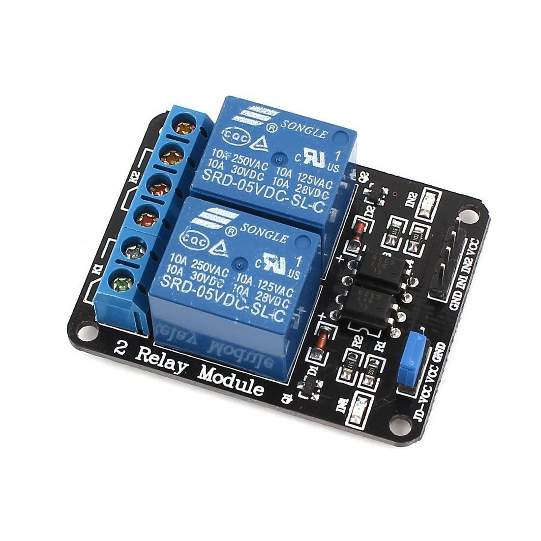
The 2 Channels Relay Module is a convenient board which can be used to control high voltage, high current load such as motor, solenoid valves, lamps and AC load. It is designed to interface with microcontroller such as Arduino, PIC and etc. The relays terminal (COM, NO and NC) is being brought out with screw terminal. It also comes with a LED to indicate the status of relay.
Specification:
- Digital output controllable
- Compatible with any 5V microcontroller such as Arduino.
- Rated through-current: 10A (NO) 5A (NC)
- Control signal: TTL level
- Max. switching voltage 250VAC/30VDC
- Max. switching current 10A
- Size: 50mm x 38mm x 17mm
Package includes:
- 1 x 2 Channels 5V Relay Module
Pinout

Control Pins:
VCC pin provides power to the built-in optocouplers and, optionally, the relay’s electromagnet (if you keep the jumper in place). Connect it to the 5V pin on the Arduino.
GND is the common ground pin.
IN1 & IN2 pins control the relay. These are active low pins, which means that pulling them LOW activates the relay and pulling them HIGH deactivates it.
Power Supply Selection Pins:
JD-VCC provides power to the relay’s electromagnet. When the jumper is in place, JD-VCC is shorted to VCC, allowing the electromagnets to be powered by the Arduino’s 5V line. Without the jumper cap, you’d have to connect it to a separate 5V power source.
VCC pin is shorted to the JD-VCC pin with the jumper cap on. Keep this pin disconnected if you remove the jumper.
GND is the common ground pin.
Output Terminals:
COM terminal connects to the device you intend to control.
NC terminal is normally connected to the COM terminal, unless you activate the relay, which breaks the connection.
NO terminal is normally open, unless you activate the relay that connects it to the COM terminal.
Wiring
Warning:
This board interacts with HIGH AC voltage. Improper or incorrect use could result in serious injury or death. Therefore, it is intended for people who are familiar with and knowledgeable about HIGH AC voltage.
Begin by connecting the module’s VCC pin to the Arduino’s 5V pin and the GND pin to ground. We will only be using one relay for our experiment, so connect digital pin #6 to the IN1 input pin.
You’ll also need to connect the relay module to the AC-powered device you want to control, in this case, a lamp. You’ll need to cut your live AC line and connect one end of the cut wire (coming from the wall) to COM and the other to NC or NO, depending on what you want your device’s initial state to be.
If you want to keep your device off most of the time and turn it on occasionally, connect the other end of the wire to NO. Otherwise, connect it to NC.
For this project, we want our lamp to be off at first and then turn on when we activate the relay, so we will connect one end of the wire to COM and the other to NO.
The following illustration shows the wiring.
We left the jumper in place in the above wiring diagram, so the relay’s electromagnet will be driven directly from the Arduino. In this case, the relay module and the Arduino will not be physically isolated.
If you want to keep them isolated, you must provide a separate 5V power supply voltage to the JD-VCC and GND. The wiring below shows how to accomplish this.

Code
Controlling a relay module with the Arduino is as easy as controlling an LED. Here’s a simple code that will activate the relay for 3 seconds and then deactivate it for 3 seconds.
int RelayPin = 6;

void setup() {
	// Set RelayPin as an output pin
	pinMode(RelayPin, OUTPUT);
}

void loop() {
	// Let's turn on the relay...
	digitalWrite(RelayPin, LOW);
	delay(3000);

	// Let's turn off the relay...
	digitalWrite(RelayPin, HIGH);
	delay(3000);
}
Code Explanation:
The sketch begins by declaring the pin to which the relay module’s input pin is connected.
int RelayPin = 6;In the setup function, we configure the input pin to behave as an output.
pinMode(RelayPin, OUTPUT);In the loop function, we turn the device ON/OFF by pulling the relay pin LOW/HIGH.
digitalWrite(RelayPin, LOW) pulls the pin LOW, whereas digitalWrite(RelayPin, HIGH) pulls the pin HIGH.
digitalWrite(RelayPin, LOW);
delay(3000);

digitalWrite(RelayPin, HIGH);
delay(3000);