Description
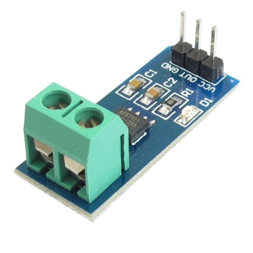
The ACS712 Current Sensor Module 20A Version is essential for precise electrical current measurements. This module is designed to accurately measure both AC and DC currents up to 20 Amperes. With its compact form factor and easy integration, it is ideal for various applications, including power monitoring, energy management, and industrial automation. The ACS712 utilizes Hall effect technology, ensuring reliable and non-intrusive current sensing. It provides an analog output voltage proportional to the measured current, making it compatible with microcontrollers and data acquisition systems. Trust the ACS712 Current Sensor Module 20A Version for dependable and efficient current measurements in your projects.
Package Includes:
- 1x ACS712 Current Sensor 20A Version
Features:
- 5VDC operating voltage: The module operates at 5 volts, which is commonly available from microcontrollers (MCUs) and other power sources.
- Operating voltage with LED: The module includes an LED indicator that shows the operating voltage status, providing a visual indication of its power supply.
- Pin 5V power supply with on-board indicator: It has a dedicated pin for connecting a 5V power supply, and there is an on-board indicator to easily monitor the power status.
- Measures positive and negative 20 amps: The module is capable of accurately measuring both positive and negative currents up to 20 amps. The analog output is directly proportional to the measured current, with a scaling factor of 100 mV per amp.
- Output voltage stability: When no test current is flowing, the output voltage remains stable at VCC/2, ensuring a reliable and consistent offset voltage.
- Low-noise analog signal path: The module utilizes a low-noise analog signal path, minimizing any interference and ensuring accurate and precise current measurements.
- Adjustable device bandwidth: The device bandwidth can be adjusted using the FILTER pin, allowing you to customize the module's response and filtering characteristics based on your specific requirements.
- Near zero magnetic hysteresis: The module is designed with near zero magnetic hysteresis, meaning it accurately senses currents without being affected by magnetic interference.
- High DC Power Supply Rejection Ratio (PSRR): It has a high PSRR, enabling reliable operation even with low-accuracy power supplies or batteries in the range of 3 to 4.5 volts. This makes it suitable for applications where power supply quality may vary.
Description:
the ACS712 Current Sensor Module 20A Version - a versatile and reliable solution for accurate current measurements. This module operates at a 5VDC voltage, making it compatible with power supplies from microcontrollers (MCUs). It also features an on-board power indicator for easy monitoring. With its wide current measuring range of positive and negative 20 amps, it provides an analog output of 100 mV/A, allowing precise current readings. The ACS712 Current Sensor Module boasts a unique feature where the output voltage remains at VCC/2 when no test current is passing through. This ensures a stable output offset voltage, eliminating any inaccuracies in measurement. Its low-noise analog signal path guarantees accurate and clear readings, while the device bandwidth can be adjusted using the new FILTER pin, allowing for fine-tuning according to specific requirements. Furthermore, this module exhibits near-zero magnetic hysteresis, enabling precise current sensing without interference. It also offers high DC Power Supply Rejection Ratio (PSRR), allowing reliable operation even with low-accuracy power supplies or batteries ranging from 3 to 4.5 V. Trust the ACS712 Current Sensor Module 20A Version for precise, stable, and efficient current measurements in a wide range of applications, from power monitoring to industrial automation.
Principle of Work:
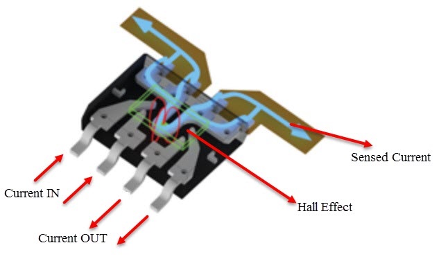
The ACS712 Current Sensor Module is based on the Hall Effect principle. Inside the module, there is a copper strip that connects the IP+ (positive input) and IP- (negative input) pins. This copper strip acts as a conductor for the current being measured. When electric current passes through the copper strip, it generates a magnetic field around it. The Hall Effect sensor, which is integrated into the module, is sensitive to this magnetic field. The Hall Effect sensor detects the magnetic field and converts it into a corresponding voltage signal. This voltage signal represents the measured current and is available at the output pin of the module. Importantly, the ACS712 module is designed to ensure complete isolation between the input (current-carrying copper strip) and the output (voltage signal). This isolation guarantees safety and prevents any interference between the measured current and the measurement circuit. For the ACS712 Current Sensor Module 20A Version specifically, it has been optimized to accurately measure currents within the range of +/- 20A. This means it can handle currents up to 20A in either direction (positive or negative). The module's output sensitivity is specified as 100 mV per ampere (100 mV/A). This indicates that for every ampere of current flowing through the copper strip, the module's output voltage will increase by 100 millivolts.
|
ACS712 Model |
Optimized Current Range |
Output Sensitivity |
|
ACS712 ELC-20
|
+/- 20A
|
100 mV/A |

Pinout of the Board:

- VCC: This pin is used to supply power to the module and requires a 5-volt power source. It ensures the module has the necessary voltage to operate properly.
- GND: The GND pin is the ground connection, providing the reference potential for the module and completing the electrical circuit.
- OUT: The OUT pin is where the module outputs the measured current information. The output is in the form of an analog voltage signal. The magnitude of the voltage corresponds to the intensity of the measured current. By connecting this pin to an analog input of a microcontroller or other compatible device, the current readings can be read and further processed.
Applications:
- Electrical load detection and management: The module can be used to monitor the current flowing through electrical loads. By measuring and analyzing the current, it enables the detection of abnormal or excessive loads. This information can be utilized for load management, ensuring efficient operation and preventing overload conditions.
- Switched-mode power supplies (SMPS): The ACS712 module is commonly employed in SMPS designs. It allows for precise current sensing, enabling feedback control and regulation of the power supply. This helps optimize the efficiency and stability of the SMPS, enhancing overall performance.
- Protection for over-current: The module plays a vital role in over-current protection systems. By continuously monitoring the current levels, it can detect over-current conditions that may pose risks to electrical equipment or systems. Once an over-current event is detected, appropriate protective measures can be implemented, such as triggering circuit breakers or shutting down the power supply to prevent damage.
- Battery charging and monitoring: In battery charging applications, the ACS712 module can be used to measure the charging current flowing into the battery. This allows for accurate monitoring of the charging process, ensuring optimal charging rates and preventing overcharging or undercharging of the battery.
- Motor control and robotics: The module is commonly employed in motor control systems, including robotics and automation. By measuring the current supplied to motors, it enables precise control and monitoring of motor performance. This can be used for speed control, torque control, and detecting anomalies such as motor stalls or excessive loads.
- Energy monitoring and metering: The ACS712 module plays a significant role in energy management and metering applications. By measuring the current consumption of appliances, equipment, or entire systems, it enables accurate energy monitoring and allows for the calculation of power usage. This information is valuable for energy conservation, cost management, and identifying energy-intensive areas for optimization.
Circuit:

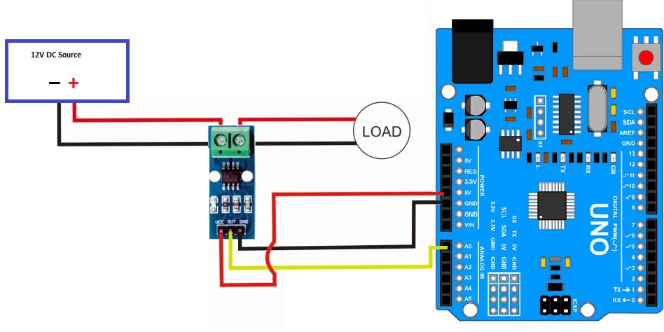
To measure the current flowing from a 12V power supply to a 12V DC lamp using the ACS712 Current Sensor Module, a wiring diagram can be set up as follows:
- Connect the GND (ground) of the 12V DC power supply to the GND terminal of the load (lamp) to complete the ground connection.
- Connect the VCC (positive) terminal of the 12V DC power supply to one terminal of the current terminal of the ACS712 module. The other terminal of the current terminal should be connected to the VCC input of the load (lamp), ensuring the current path is through the module.
- Connect the VCC (5V) pin of the ACS712 module to a 5V pin on the Arduino board. This provides the required power supply to the module.
- Connect the GND (ground) pin of the ACS712 module to a GND pin on the Arduino board, establishing the common ground reference.
- Connect the OUT pin of the ACS712 module to the A0 (analog input) pin on the Arduino board. This allows the Arduino to read the analog voltage output from the module, which corresponds to the measured current.
Library:.
To download and add the ACS712 library to the Arduino IDE, you can follow these steps:
- Download the ACS712 library by clicking on the following link: ACS712 Library.
- Save the downloaded zip file to a location on your computer.
- Open the Arduino IDE.
- From the menu, go to "Sketch" > "Include Library" > "Add .ZIP Library".
- Locate and select the downloaded ACS712 library zip file.
- Click the "Open" button to import the library into the Arduino IDE.
- After successfully adding the library, you can now use the ACS712 functions and examples in your Arduino projects.
Code:
This code reads the AC current value from the ACS712 sensor, filters out low currents, and displays the current value in the serial monitor. It also demonstrates an example of triggering an action or displaying a message based on a specific current threshold.
#include "ACS712.h"

ACS712 sensor(ACS712_20A, A0);

void setup() {
  Serial.begin(9600);
  sensor.calibrate();
}

void loop() {
  float I = sensor.getCurrentAC();

  // Ignore values below 0.09 for better accuracy
  if (I < 0.09) {
    I = 0;
  }

  Serial.print("Current: ");
  Serial.print(I);
  Serial.println(" A");

  // Additional functions in the serial monitor
  if (I >= 5.0) {
    Serial.println("High current detected!"); // Example: trigger an action for high current
  }

  // Add more conditional statements for other actions or thresholds

  delay(300);
}-
#include "ACS712.h": This line includes the ACS712 library, which provides the necessary functions and definitions to interface with the ACS712 Current Sensor Module. -
ACS712 sensor(ACS712_20A, A0);: This line initializes an instance of the ACS712 class named "sensor". It specifies the ACS712_20A model and the analog pin A0 as the input pin for the sensor module. -
void setup(): This function is executed once at the start of the program. It sets up the initial configuration. -
Serial.begin(9600);: This line initializes the serial communication with a baud rate of 9600, allowing communication between the Arduino board and the computer via the USB connection. This is necessary for displaying output in the serial monitor. -
sensor.calibrate();: This line calibrates the ACS712 sensor. It is used to establish the zero current reference point and should be called during the setup phase. -
void loop(): This function is executed repeatedly after the setup phase. -
float I = sensor.getCurrentAC();: This line retrieves the AC current value from the ACS712 sensor and stores it in the variable "I". ThegetCurrentAC()function returns the current value in amperes. -
if (I < 0.09) { I = 0; }: This conditional statement is used to filter out low current values below 0.09A, improving accuracy. If the current is below the threshold, it is set to zero. -
Serial.print("Current: ");,Serial.print(I);, andSerial.println(" A");: These lines output the current value in the serial monitor. It prints the label "Current: " followed by the current value in amperes, and then adds a line break. -
if (I >= 5.0) { Serial.println("High current detected!"); }: This conditional statement checks if the current value is equal to or greater than 5.0A. If it is, it prints "High current detected!" in the serial monitor. This is an example of triggering an action or displaying a message based on a specific current threshold. -
delay(300);: This line introduces a delay of 300 milliseconds between iterations of the loop function. It slows down the rate of current readings to avoid overwhelming the serial monitor with data.
Technical Details:
- Measuring range ± 20A / DC
- Analog output 100 mV/A
- no current flows - output voltage is ~ VCC / 2
- 1.2 mΩ internal conductor resistance
- Total output error of 1.5% at TA = 25°C
- 80kHz bandwidth
- Dimensions PCB: L x W x H approx. 27.5 x 11.6 x 14 mm
Resources:
Comparisons:
There are three variants of ACS712 Sensor based on the range of its current sensing. The optimized ranges are +/-5A, +/-20A, and +/-30A. these 3 variants are different not only from the current point of view but also all have the same IC but with a different configuration, so when you want to measure a higher current you will sacrifice some of the resolutions depending on the variant, the output sensitivity also varies :
-
ACS712 20A Module:
- Current Measurement Range: +/- 20 Amperes
- Output Sensitivity: 100 mV/A
- Optimized for applications where current measurements up to 20A are required.
-
ACS712 30A Module:
- Current Measurement Range: +/- 30 Amperes
- Output Sensitivity: 66 mV/A
- Designed for applications that demand current measurements up to 30A.
-
ACS712 5A Module:
- Current Measurement Range: +/- 5 Amperes
- Output Sensitivity: 185 mV/A
- Suitable for applications requiring current measurements up to 5A.
The table below summarizes the key specifications of these ACS712 modules:
| ACS712 Module | Current Measurement Range | Output Sensitivity |
|---|---|---|
| ACS712 20A | +/- 20 Amperes | 100 mV/A |
| ACS712 30A | +/- 30 Amperes | 66 mV/A |
| ACS712 5A | +/- 5 Amperes | 185 mV/A |
It's important to note that the choice of the module depends on the specific application requirements and the expected current levels to be measured. Selecting the appropriate module ensures accurate and reliable current measurements within the desired range.

