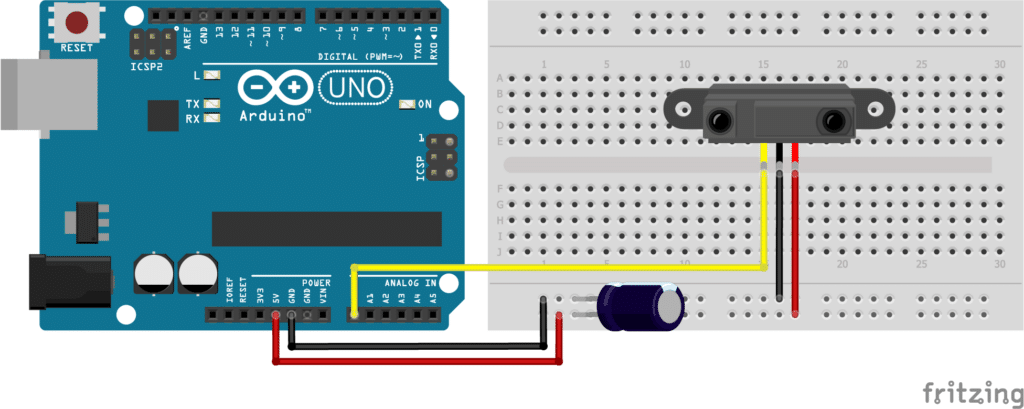
Description
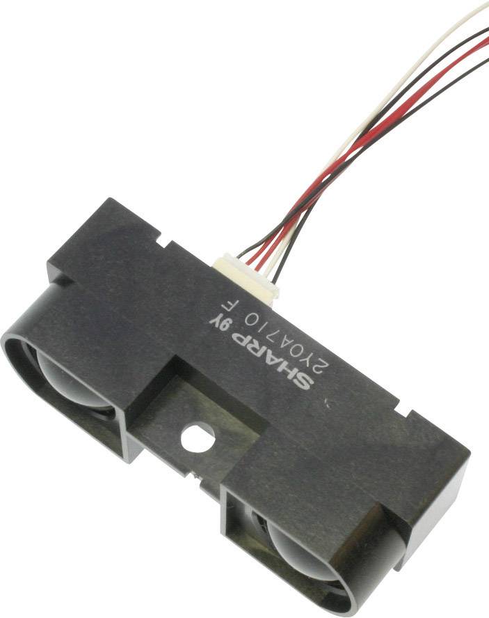
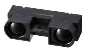
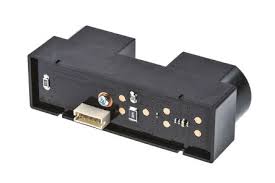
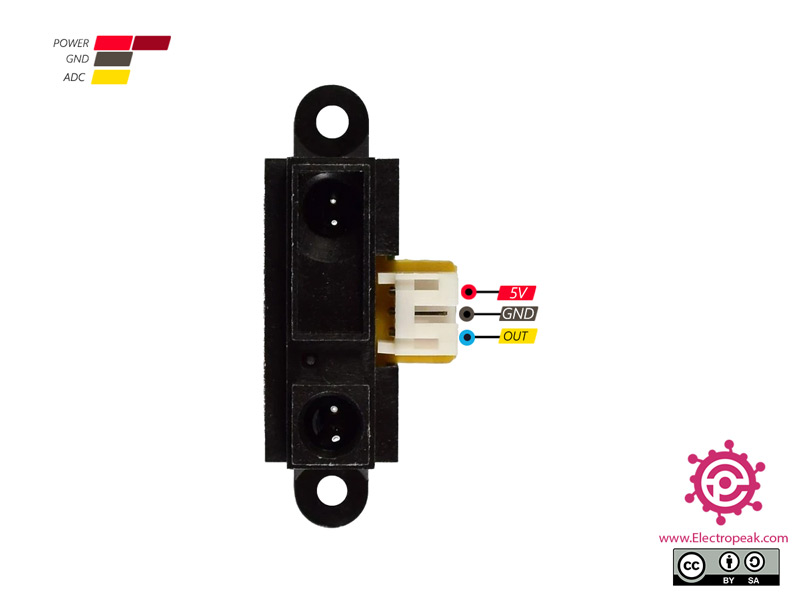
GP2Y0A21YK0F is a distance-measuring sensor unit composed of an integrated combination of PSD (position-sensitive detector), IRED (infrared-emitting diode), and signal processing circuit. This device outputs the voltage corresponding to the detection distance, so this sensor can also be used as a proximity sensor.
Features
- The measuring and detecting distance is 10 to 80 cm
- The maximum allowable Angle : > 40 °
- The power supply voltage : 4.5 to 5.5 V
- The average power consumption : 35 mA
- Peak power consumption : about 200 mA
- The frequency of updates : 25 Hz/40 ms
- Analog output noise : < 200 mV
- Less influence on the color of reflective objects, reflectivity
- Line-up of distance output/distance judgement type:
- Distance output type (analog voltage) : GP2Y0A21YK
- Distance judgement type : GP2Y0D21YK
- The judgment distance is 24 cm
- Adjustable within the range of 10 to 80cm (optionally available)
- External control circuit is unnecessary
- Low cost
How does an IR distance sensor work?
An IR distance sensor uses a beam of infrared light to reflect off an object to measure its distance. The distance is calculated using the triangulation of the beam of light. The sensor consists of an IR LED and a light detector, or PSD (Position Sensing Device). When the beam of light gets reflected by an object, the reflected beam will reach the light detector, and an ‘optical spot’ will form on the PSD.
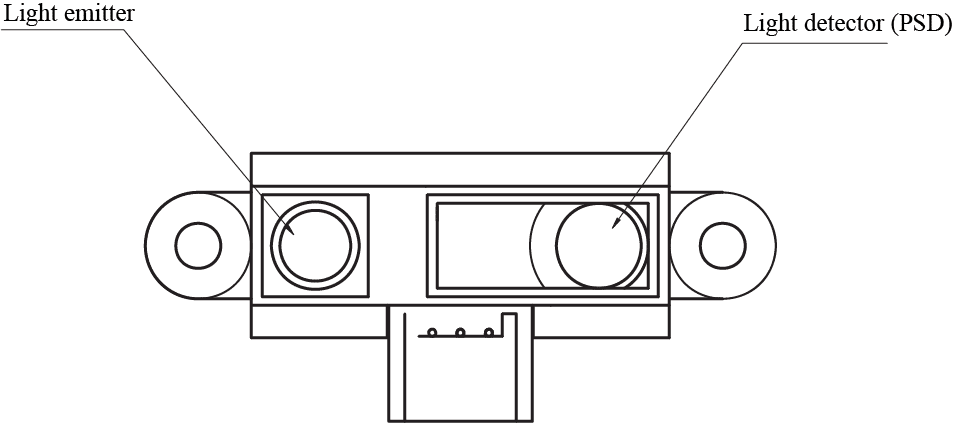 When the position of the object changes, the angle of the reflected beam and the position of the spot on the PSD change as well. See points A and B in the image below.
 Note the change in the angle of the reflected beam and the position of the ‘optical spot’ on the PSD.
The sensor has a built-in signal processing circuit. This circuit processes the position of the optical spot on the PSD to determine the position (distance) of the reflective object. It outputs an analog signal which depends on the position of the object in front of the sensor.
How to read an IR distance sensor?
IR distance sensors output an analog signal, which changes depending on the distance between the sensor and an object. From the datasheet, you can see that the output voltage of the SHARP GP2Y0A21YK0F ranges from 2.3 V when an object is 10 cm away to 0.4 V when an object is 80 cm away. The graph also shows why the usable detection range starts at 10 cm. Notice that the output voltage of an object that is 2 cm away is the same as the output voltage for an object that is 28 cm away. The usable detection range, therefore, starts after the peak at roughly 10 cm or 2.3 V.
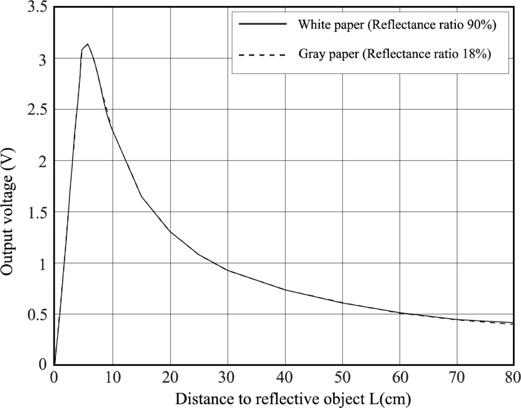
The graph also shows the drawback of these sensors, the response is non-linear. In other words, a big change in the output voltage does not always correspond to a big change in range. In order to determine the distance between the sensor and an object, you need to find a function that converts the output voltage into a range value.
This can be done using MS Excel and results in the following formula for distances > 10cm:
Distance (cm) = 29.988 X POW (Volt, -1.173)
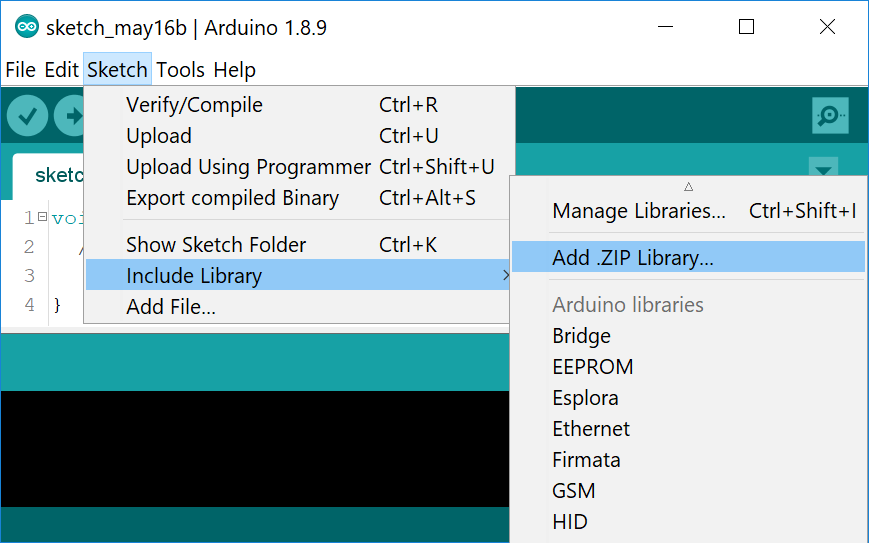
This is the function that is used in the SharpIR library, which we will be using later. Note that this function is based on data from the SHARP datasheet only. The output characteristics of the sensor will vary slightly from sensor to sensor so you might get inaccurate readings.
If you want to improve the accuracy of your readings, you can try to measure and plot many data points in Excel and fit a curve through these points. Once you have a new function for your specific sensor, you will need to change the formula used in the SharpIR.cpp file.
GP2Y0A21YK0F Specifications
| Operating voltage | 4.5 to 5.5 V |
| Operating current | 30 mA |
| Measuring range | 10 to 80 cm |
| Output type | Analog |
| Dimensions | 29.5 x 13 x 13.5 mm |
| Mounting holes | 2x 3.2 mm, 37 mm spacing |

