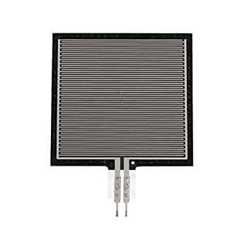
Description
RP-S40-ST High Accuracy Thin Film Pressure Sensor Force Sensor for Intelligent High-end Seat 20g-10kg
Features:
The flexible sensor has the characteristics of flexible ultra-thin, ultra-low power consumption and extreme speed response, etc.
Small size, this flexible pressure sensor is based on new nanometer pressure-sensitive materials supplemented by ultra-thin film substrate.
This pressure sensor has the characteristic of high stability, high consistency.
Highly sensitive flexible nanometer materials can realize highly sensitive detection of pressure.
When sensor detects outside pressure, the resistance of sensor will change.
Pressure signal can be converted into a corresponding electrical signal output using simple circuit.
Specifications:
Model: RP-S40-ST
Manufacturing process: thin film
Output signal: analog
Pressure induction range: 20g-10kg
Trigger: 20 g, default resistance <200kΩ, trigger
Thickness: 0.45mm
Not trigger resistance: > 10MΩ
Activation time: <0.01s
Delay: +10%, (RF+-RF-)/FR+,1000g force
Response time: < 10ms
Size: 5 x 4cm / 1.97 x 1.57in
Weight: 2g
As described above, the RP-S40-ST is to be wired to the Arduino board using a voltage divider configuration with a 4.7kΩ resistor. Thus, the main components required to follow along in this tutorial are as follows:
-
1x 40mm Force Sensing Resistor
-
1x 4.7kΩ Resistor
-
1x Arduino Uno Board
-
5x Jumper Wires (Male-to-Male)
-
1x Mini Breadboard
-
1kg Calibrated Masses Kit
It is recommended that the FSR is either soldered (be careful, the FSR can get damaged if heated too much) or attached to a breadboard directly. The problem with wiring the FSR directly to a breadboard is that it creates an awkward setup. Thus, we solder ours directly to jumper wires and place heat shrink around the connections.
The wiring diagram is given below, which follows the recommendation of a voltage divider established between the FSR and a 4.7kΩ resistor. The Arduino is measuring the voltage drop across the 4.7kΩ resistor:

Now that the Arduino is wired to the FSR voltage divider circuit, we can begin to take test measurements and investigate the response of the FSR and how it behaves in reference to the calibration discussed in the previous section.
The datasheet for the RP-S40-ST cites a range of 10g - 10kg, but 10kg is fairly large to calibrate without a force tester (which we do not have in our lab!). Thus, the testing region for the FSR in this case is 20g - 1.1kg (more on this later). First, an Arduino code must be created which prints out resistance values from the FSR. This code is given below:
int FSR_pin = A0;    // select the input pin for the potentiometer
int avg_size = 10; // number of analog readings to average
float R_0 = 4700.0; // known resistor value in [Ohms]
float Vcc = 5.0; // supply voltage

void setup() {
  Serial.begin(9600);
}

void loop() {
  float sum_val = 0.0; // variable for storing sum used for averaging
  float R_FSR;
  for (int ii=0;ii
Once the RP-S40-ST is wired to the Arduino board and the code is uploaded, the output can be viewed in the Arduino IDE’s serial monitor and plotter. Upon pressing on the FSR, the output should decrease, as plotted above for the resistance as a function of force. For smaller forces, the response may be highly variable and non-repeatable. This is due to the uneven distribution of pressure along the FSR, in conjunction with the high resistivity at those forces. Thus, it is also recommended that a device be used that maintains consistency in its forcing area - such as a piston. This will ensure the calibration of the FSR is accurate and not misleading due to variations in forcing area. In our case, we 3D printed a 15mm x 15mm plate that will hold the calibrated masses to be added atop the FSR. The 3D printed plate weighs roughly 6g, which is accounted for in all calculations (weight was measured by a load cell).
A demo of the code above is shown in the video below:


