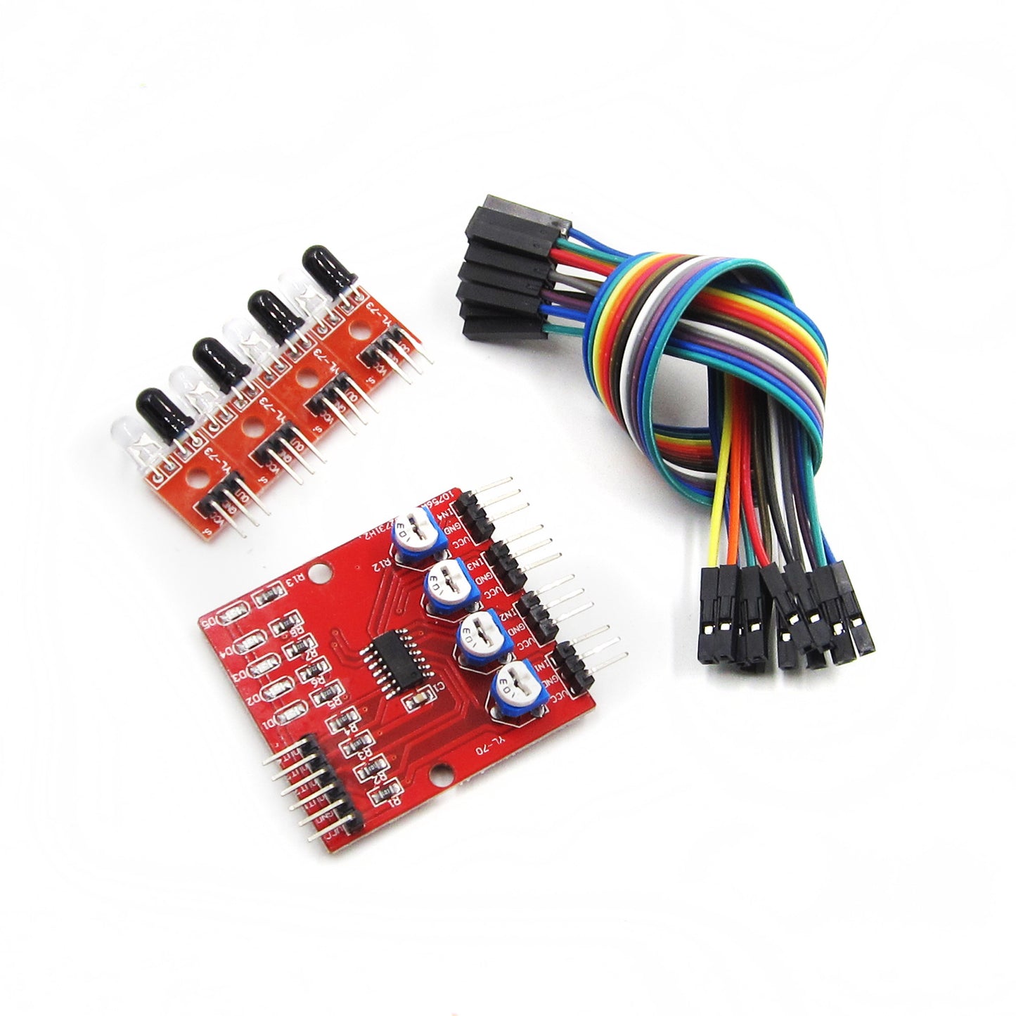
Description
The 4-Channel Line Tracker sensor provides an easy way for line tracking. A line sensor is composed of a number cells and each cell is composed of a sender and a receiver. The particularity of this sender/receiver pair is that it sends light that shall be reflected by the line to be detected but not by the eventually opaque background surrounding this line. Any sender/receiver pair that is able to make a difference between a line and the rest of ground (of a different color) can be used in a line sensor.
VCC pin is connected to 5V , GND pin is connected to the GND, S1, S2, S3, and S4 pins are connected to the digital I/O pins 2 – 5 but you can use others
Features
- Operating voltage: DC 3.3V-5V
- Operating Current:>1A
- Operating temperature: -10 C – +50 C
- Mounting Hole: M3 screws
- Detection distance: 1mm to 60 CM adjustable, the closer the distance,the more stable performance, and white reflection farthest.
- Output Interface: 6-wire (1234: signal output, +: positive supply -: ground)
- Output signal: TTL level
Pin Connections:

Sample Project:
Circuit:
- Required Materials:
- Arduino UNO R3 × 1
- 4 Channel IR Obstacle Avoidance Proximity Module × 1
- Male to Male jumper wire × 1
- Male to Female jumper wire × 1
- Interfacing with Arduino:

Library:
- No external library is required for this module to work.
Code:
// constants won't change. They're used here to set pin numbers:
const int sensor1 = 2;


int val = 0;

void setup()
{
    Serial.begin(9600);
    pinMode(sensor1, INPUT);
}

void loop()
{
    val = digitalRead(sensor1);
    Serial.println(val);
    delay(20);
}

