

Description:
Here is the schemetics:
Package included:
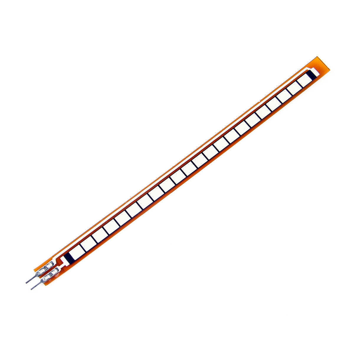
- 1 x 4.5 Inch Flex Sensor
Example Circuit
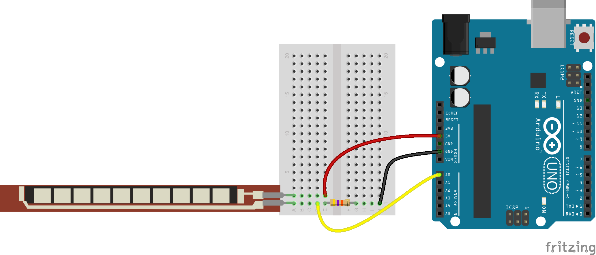
The simplest way to incorporate this sensor into your project is by using it in a voltage divider. This circuit requires one resistor. Many values from 10KΩ to 100KΩ will work. If you have a resistor kit, you may want to introduce some trial-and-error to hone in on that perfect static resistance.
A value between the minimum and maximum resistance values is usually a good choice. We'll use a 47kΩ resistor in this example. Here's the hookup:
And a schematic:
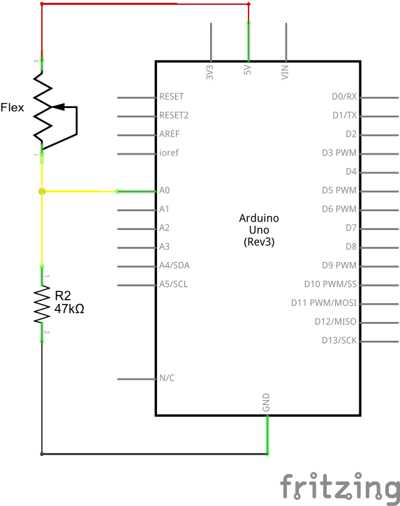
The 47kΩ resistor on the ground side, and the flex sensor on the 5V side, means as the flex sensor's resistance increases (meaning the sensor is bending) the voltage on A0 will decrease.
Example Program
Here is a simple Arduino example based on the circuit above. Copy and paste this into your Arduino IDE, then upload!
const int FLEX_PIN = A0; // Pin connected to voltage divider output

// Measure the voltage at 5V and the actual resistance of your
// 47k resistor, and enter them below:
const float VCC = 4.98; // Measured voltage of Ardunio 5V line
const float R_DIV = 47500.0; // Measured resistance of 3.3k resistor

// Upload the code, then try to adjust these values to more
// accurately calculate bend degree.
const float STRAIGHT_RESISTANCE = 37300.0; // resistance when straight
const float BEND_RESISTANCE = 90000.0; // resistance at 90 deg

void setup()
{
  Serial.begin(9600);
  pinMode(FLEX_PIN, INPUT);
}

void loop()
{
  // Read the ADC, and calculate voltage and resistance from it
  int flexADC = analogRead(FLEX_PIN);
  float flexV = flexADC * VCC / 1023.0;
  float flexR = R_DIV * (VCC / flexV - 1.0);
  Serial.println("Resistance: " + String(flexR) + " ohms");

  // Use the calculated resistance to estimate the sensor's
  // bend angle:
  float angle = map(flexR, STRAIGHT_RESISTANCE, BEND_RESISTANCE,
                   0, 90.0);
  Serial.println("Bend: " + String(angle) + " degrees");
  Serial.println();

  delay(500);
}
After uploading, open your serial monitor, and set the baud rate to 9600 bps.
If you bend the flex sensor, you should see resistance and estimated angle calculations change:
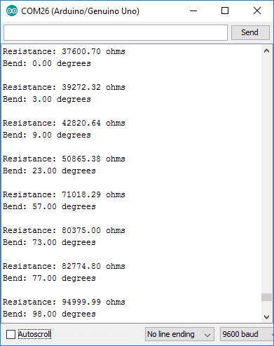
If the value's don't seem correct, make sure the constants VCC and, more importantly, R_DIV are accurate. If you used something other than a 47kΩ resistor, enter that value in for R_DIV.
Through trial-and-error, try to hone in on more accurate values for STRAIGHT_RESISTANCE and BEND_RESISTANCE -- your flex sensor's resistance when it's straight and bent at 90°.