


DESCRIPTION
Features
- Very compact size
- Low power consumption
- RoHS complaints and lead-free
- Can distinguish between smoke and dust
- Dust can be detected even by a single pulse
- Specifications
- Operating Voltage : 5V
- Max. Current : 20 mA
- Operating Temperature : -10 ~ 65°C
Package Included
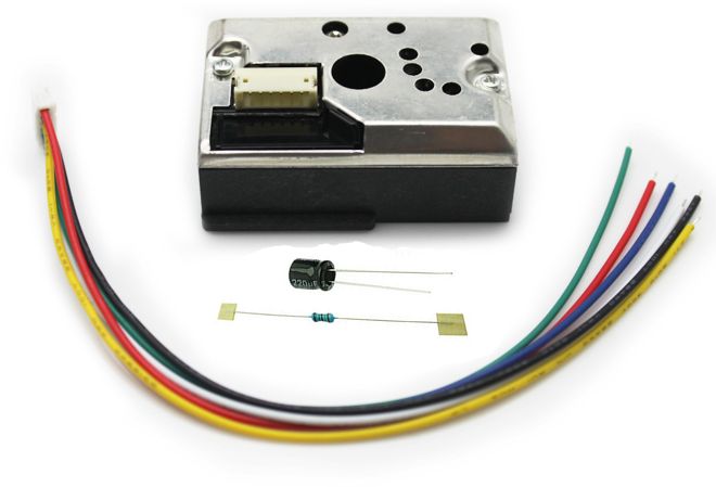
- GP2Y1010AU0F Compact Optical Dust Sensor Smoke Particle Sensor With Cable
Sensor Pinout
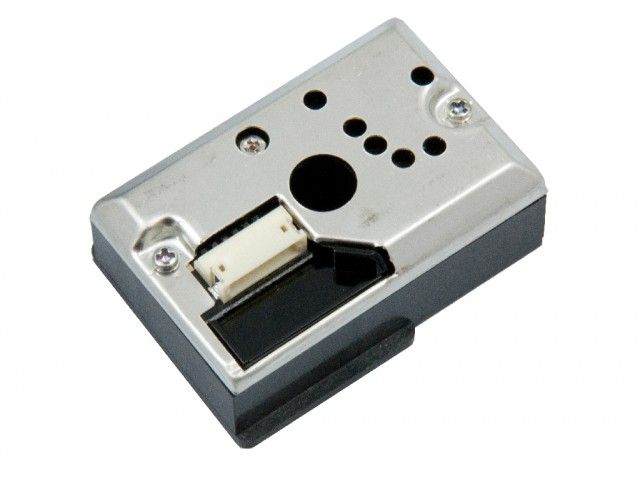
The GP2Y1014AU0F Dust Sensor module has 6 pins; those are V-LED, LED-GND, LED, S-GND, VOUT, and VCC. The output of this sensor is analog, and we need to connect this pin to the ADC of a microcontroller to measure the PM in the air. The pinout of the GP2Y1014AU0F Dust Sensor is shown below:

V-LED This is the VCC pin of the LED. Connect this pin to the 5V pin of the Arduino with a 150Ω current-limiting resistor.
LED-GND This is the ground Pin of the LED. Connect this pin to the Ground pin of the Arduino.
LED This Pin can be used to Toggle the LED On/Off. Connect it to any digital pin of Arduino.
S-GND is the ground pin of the pulse Dust Sensor module and it should be connected to the ground pin of the Arduino.
Vout This is the output of the Dust Sensor Module, you can connect it to any analog pins of the Arduino.
VCC Power Pin of the Dust Sensor Module connects to 5V or 3.3V pin of the Arduino.
How Does a GP2Y1014AU0F Dust Sensor Module Work?
The working of the GP2Y1014AU0F Dust sensor is simple and easy to understand. Inside the sensor, there are three major parts, they are the light-emitting diode(light source), the photodiode(detector), and a pair of lenses. The LED and the Photodiode inside the sensor are so placed that the two optical axis cross the detection area in the sensor. When dust or smoke enters the detection area of the sensor, the light inside the sensor gets reflected from the dust or smoke, as a result, the current generated by the photodiode varies in accordance with the amount of the detected light. And by converting and amplifying the current value to voltage value with proper circuitry we get the desired output from our sensor.

To work with the sensor you need only two pins out of all six pins. The first one triggers the LED and the second one puts out the analog signal from the sensor. Resistor, R1=150Ω, and capacitor, C1=220uF mentioned above are required for the pulse drive of the LED. Without the resistor and the capacitor, the module does not work. To get the desired data out of the sensor, you need to trigger the LED with a 10ms pulse in which the pulse width should be not more than 0.32ms. And as recommended by the datasheet, we should sample the signal after 0.28ms, after the trigger pulse is provided to the LED.
Arduino GP2Y1014AU0F Dust Sensor Circuit Connection Diagram
Now that we have a complete understanding of how a GP2Y1014AU0F Dust Sensor works, we can connect all the required wires to Arduino and then write our code to get the data out of the sensor module. The Connection Diagram of the GP2Y1014AU0F Dust Sensor with Arduino is given below.

Connecting the GP2Y1014AU0F Dust Sensor with Arduino is really simple and easy. As we know from the above discussion, this sensor gives out data by the varying voltage at the output pin. So we need to use the ADC of the Arduino to convert and compute the data to recognizable value. We also need to connect the LED enable pin of the sensor to one of the GPIO pins of the Arduino, it's the white wire that is connected to the D7 of the Arduino. Finally, we need a 150R resistor and a 220uF capacitor. The resistor and the capacitor make an RC timer circuit, in our case a pulse driver circuit that is absolutely mandatory for the stable operation of the device, and the values are recommended by the datasheet.

Arduino Code for Interfacing GP2Y1014AU0F Dust Sensor Module with Arduino
The Arduino code to process data from GP2Y1014AU0F Sensor is very simple and easy to understand. We just need to convert the analog voltage given by the sensor and convert it to digital data to get our result.
We start our code by defining the analog input pin of the device and we also define a digital pin that will be used to control the LED. Next, we have defined three variables that will hold the necessary timing values required to calculate the dust measured by the sensor. Next, we have three float variables that will hold the result generated by the sensor.
Next, we have our setup function. In the setup function, we enable the serial for debugging and we make the ledpin as output.
Next, we have our loop function; in the loop function, we start the measurement process that is recommended by the datasheet. The total measurement process takes around 10ms but the sampling period is .28ms. First, we make the ledpin low that turns on the led and we use the delayMicroseconds() function to generate a 280 uS or 0.28mS delay that is recommended by the datasheet. Then we take our sample and add another delay of 40uS, this will ensure the pulse width remains at .32ms or 320us and we sleep for the rest of the 9680uS.
Next, we calculate the voltage value from the ADC value. Please make sure that your Arduino is powered with a proper +5V supply and not powered with USB if so, you will get errors in your result.
Finally, we calculate the amount of suspended dust particles by using the linear equation provided by Chris Nafis; the unit is in ug/m3, and print the result in the serial monitor window.
#define measurePin = 0; //Connect dust sensor to Arduino A0 pin
#define ledPower = 7;   //Connect 3 led driver pins of dust sensor to Arduino D2
int samplingTime = 280; // time required to sample signal coming out of the sensor
int deltaTime = 40; //
int sleepTime = 9680;
float voMeasured = 0;
float calcVoltage = 0;
float dustDensity = 0;
void setup(){
  Serial.begin(9600);
  pinMode(ledPower,OUTPUT);
}
digitalWrite(ledPower,LOW); // power on the LED
   (samplingTime);
  voMeasured = analogRead(measurePin); // read the dust value
  delayMicroseconds(deltaTime);
  digitalWrite(ledPower,HIGH); // turn the LED off
  delayMicroseconds(sleepTime);
calcVoltage = voMeasured * (5.0 / 1024.0);
dustDensity = 170 * calcVoltage - 0.1;
Serial.println(dustDensity);
delay(1000);