Description
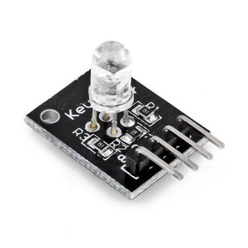
RGB LED module consists of a plug-in full color LED made by R, G, B three pin PWM voltage
input can be adjusted section three primary colors (red/blue/green) strength in order to achieve full color mixing effect. Control of the module with the Arduino can be achieved cool lighting effects.
Specifications
This module consists of a 5mm RGB LED, 3 150Ω limiting resistors to prevent burnout and 4 male header pins. Adjusting the PWM signal on each color pin will result on different colors.
| Operating Voltage | 5V |
| LED Drive Mode | Common cathode drive |
| LED Diameter | 5mm |
| Board Size | 15mm x 19mm [0.59in x 0.75in] |
Features
1. the use of plug-in full-color LED
2. RGB trichromatic limiting resistor to prevent burnout
3. through the PWM adjusting three primary colors can be mixed to obtain different colors
4. with a variety of single-chip interface
5. the working voltage: 5V
6. LED drive mode: common cathode driver
Product includes
- KY-016 RGB 3 Color Full Color LED Module
Connection Diagram
| KY-016 | Arduino |
|---|---|
| R | Pin 11 |
| B | Pin 10 |
| G | Pin 9 |
| – | GND |
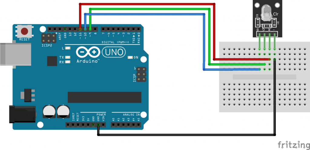
Connect the module red pin (R) to pin 11 on the Arduino. Blue (B) to pin 10, green (G) to pin 9 and ground (-) to GND.

Code
The following Arduino sketch will gradually increase/decrease the PWM values on the red, green and blue pins causing the LED to cycle through various colors.
int redpin = 11; // select the pin for the red LED
int bluepin =10; // select the pin for the  blue LED
int greenpin =9; // select the pin for the green LED

int val;

void setup() {
  pinMode(redpin, OUTPUT);
  pinMode(bluepin, OUTPUT);
  pinMode(greenpin, OUTPUT);
  Serial.begin(9600);
}

void loop() {
  for(val = 255; val > 0; val--)
  {
    analogWrite(11, val);
    analogWrite(10, 255 - val);
    analogWrite(9, 128 - val);

    Serial.println(val, DEC);
    delay(5);
  }
  for(val = 0; val < 255; val++)
  {
    analogWrite(11, val);
    analogWrite(10, 255 - val);
    analogWrite(9, 128 - val);

    Serial.println(val, DEC);
    delay(5);
  }
}

