

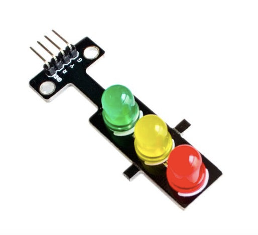
Description:
This is a mini-traffic light display module, high brightness, very suitable for the production of traffic light system model. It is featured with its small size, simple wiring, targeted, and custom installation. It can be connected PWM to control the brightness of the LED.
Features
- Size: 56 x 21 x 11mm
- Fixing hole: 3mm
- Pitch: 15mm
- Color: red yellow green
- LED: 8mm x 3
- Brightness: Normal brightness
- Voltage: 5V
- Input: Digital level
- Interface: common cathode, red, yellow and green separate control
- Platform: , microcontroller
LED Traffic Light Module Tutorial
This is a mini-traffic light display module, high brightness, very suitable for the production of traffic light system model. It is featured with its small size, simple wiring, targeted, and custom installation. It can be connected PWM to control the brightness of the LED.
Before you are getting started, prepare all the item needed:
- Arduino UNO
- LED traffic light module
- Jumper wires
- Breadboard
Sample Code
/*MYBOTIC TRAFFIC LIGHT PEDESTRIAN CONTROL*/
#define RED_SET_TIME 5000
#define YELLOW_SET_TIME 2000
#define GREEN_SET_TIME 5000
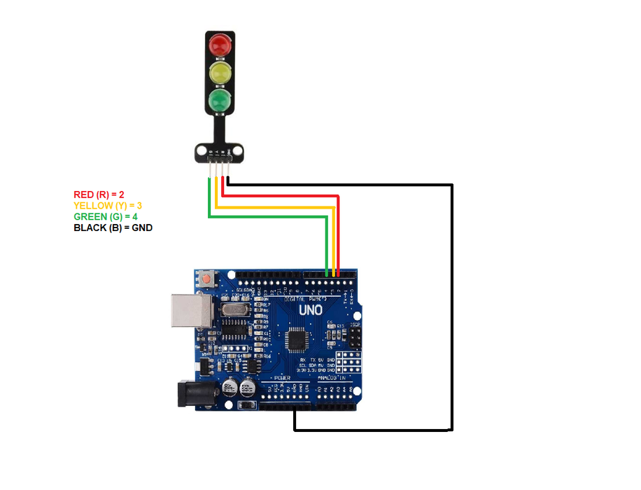
#define LIGHT_1_RED 2
#define LIGHT_1_YELLOW 3
#define LIGHT_1_GREEN 4
#define GREEN_LIGHT 0
#define YELLOW_LIGHT 1
#define RED_LIGHT 2
unsigned long gulStart_Timer = 0;
unsigned short gusSet_Time[3] = {GREEN_SET_TIME, YELLOW_SET_TIME, RED_SET_TIME};
short gsWhich_Light_Index = GREEN_LIGHT;
void setup()
{
Serial.begin(9600);
pinMode(LIGHT_1_RED, OUTPUT);
pinMode(LIGHT_1_YELLOW, OUTPUT);
pinMode(LIGHT_1_GREEN, OUTPUT);
digitalWrite(LIGHT_1_GREEN, HIGH);
digitalWrite(LIGHT_1_YELLOW, LOW);
digitalWrite(LIGHT_1_RED, LOW);
gulStart_Timer = millis();
}
// the loop function runs over and over again forever
void loop()
{
if((millis()-gulStart_Timer) >= gusSet_Time[gsWhich_Light_Index])
{
gsWhich_Light_Index++;
if(gsWhich_Light_Index > RED_LIGHT)
{
gsWhich_Light_Index = GREEN_LIGHT;
}
gulStart_Timer = millis();
if(gsWhich_Light_Index == GREEN_LIGHT)
{
digitalWrite(LIGHT_1_GREEN, HIGH);
digitalWrite(LIGHT_1_YELLOW, LOW);
digitalWrite(LIGHT_1_RED, LOW);
}
else if(gsWhich_Light_Index == YELLOW_LIGHT)
{
digitalWrite(LIGHT_1_GREEN, LOW);
digitalWrite(LIGHT_1_YELLOW, HIGH);
digitalWrite(LIGHT_1_RED, LOW);
}
else if(gsWhich_Light_Index == RED_LIGHT)
{
digitalWrite(LIGHT_1_GREEN, LOW);
digitalWrite(LIGHT_1_YELLOW, LOW);
digitalWrite(LIGHT_1_RED, HIGH);
}
}
}
Uploading

After open the code in Arduino IDE, go to the [Tools] --> [Boards Manager] --> select [Arduino/Genuino UNO] as we using Arduino UNO in this tutorial.
Then connecting the Arduino UNO to PC, after that select the correct port (go to [Tools] --> [Port] --> Select correct port for Arduino UNO).
Next, compile and upload the code into your Arduino UNO.
Output
