Skip to product information
1 of 1

Blue PCB Electronics

1B13 TTP229 16-Channel Digital Capacitive Switch Touch Sensor Module

1B13 TTP229 16-Channel Digital Capacitive Switch Touch Sensor Module

Regular price Dhs. 20.00
Regular price Sale price Dhs. 20.00
Sale Sold out
View full details

Description

Keypads are one of the most popular components that are widely used in electronics. Everybody can communicate with different systems through switches. Normally, every key occupies one digital pin of the microcontroller. But by using a 4×4 keypad, you can reduce the number of occupied pins. With this module, you can use all 16 switches by occupying only 2 pins of the microcontroller.

Documentation: TTP229 datasheet

This 16-key capacitive touch keypad is based on the TTP229 IC. Output pins 1 to 8 are for direct switching on and off keys 1 to 8. There are also 2 serial pins to use the 16-key mode.

TTP229 Capacitive Touch Keypad

How it works

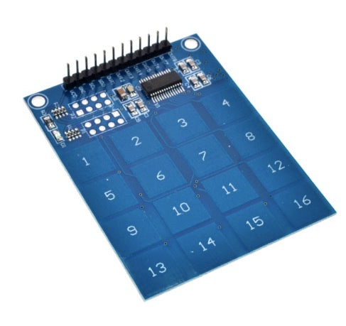
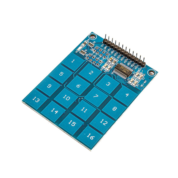
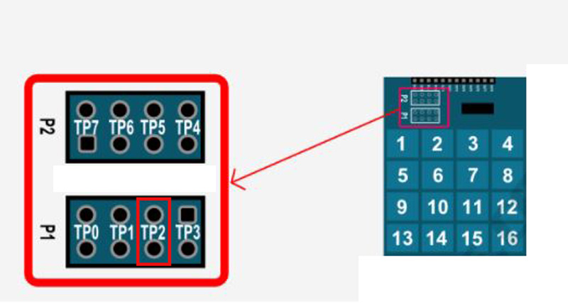
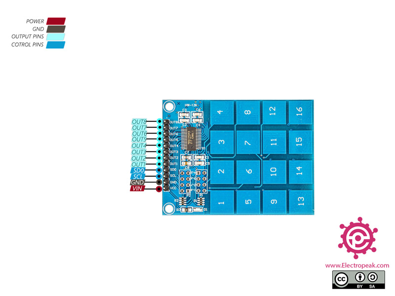
The 4×4 Keypad features a total of 16 buttons in matrix form. This module can be adjusted in different modes. The most important ones are as follows:

  • Two TP2 pins are open-circuit. In this mode, only 8 output pins are active to use 8 touch keys. By touching each key, its relevant pin becomes HIGH, and by releasing it, it becomes LOW again.
  • Two TP2 pins are short-circuiting; in this mode, two serial pins are active to use all 16 touch keys. You can only touch one key at a time.

TTP229 Capacitive Touch Keypad Pinout

This module has 12 pins:

  • VCC: Module power supply: 2.4-5.5V
  • GND: Ground
  • SCL: Input pin for Serial Clock
  • SD0: Output pin for Serial Clock
  • Out1: Digital Output pin 1
  • Out2: Digital Output pin 2
  • Out3: Digital Output pin 3
  • Out4: Digital Output pin 4
  • Out5: Digital Output pin 5
  • Out6: Digital Output pin 6
  • Out7: Digital Output pin 7
  • Out8: Digital Output pin 8

You can see the pinout of this module here.

Required Materials

Hardware Components

Arduino UNO R3 × 1
4x4 TTP229 Capacitive Touch Keypad × 1
Male to Female Jumper wire × 1

Software Apps

Arduino IDE

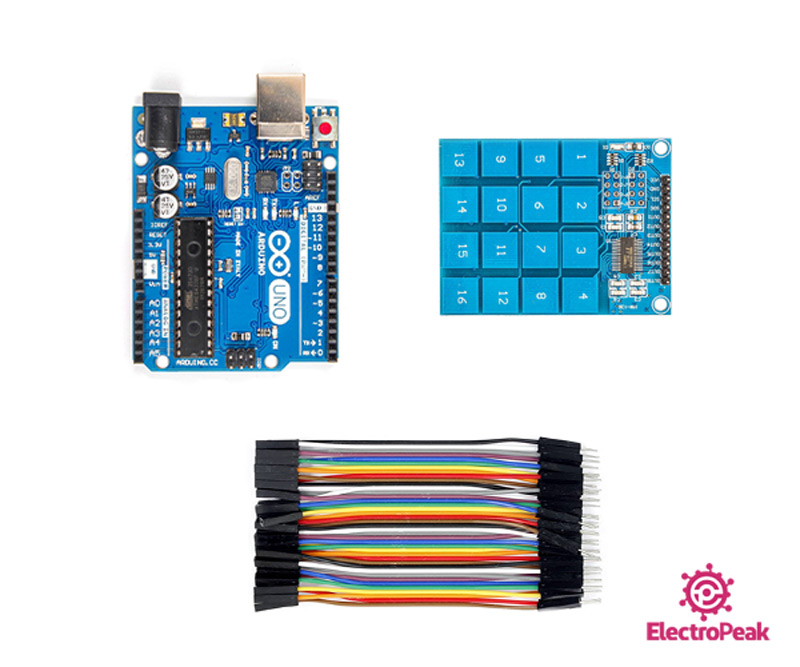
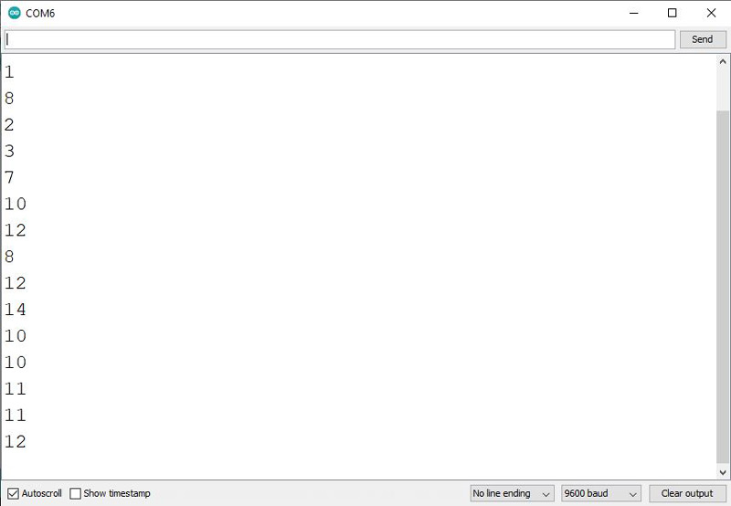
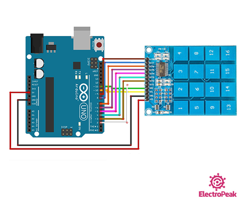
Interfacing 4x4 TTP229 Capacitive Touch Keypad with Arduino

Step 1: Circuit

The following circuit shows how you should connect Arduino to TTP229 module. Connect wires accordingly.

TTP229 Module Arduino circuit

Step 2: Code for 8 Key Mode

Upload the following code to Arduino. Note that for this mode, two TP2 pins must be open-circuit.


void setup(){
  for(int x=2;x<10;x++)
  pinMode(x,INPUT);
  Serial.begin(9600);
}

void loop(){
  for(int y=2;y<10;y++){
    if (digitalRead(y)==HIGH)
    Serial.println(y-1);
  }
}
  

In this code, we have connected 8 Arduino pins (2 to 9) to the 8 buttons of the module, and by touching each key, its number will appear in the Serial Monitor.


Step 3: Code for 16 Key Mode

Upload the following code to Arduino. Note that for this mode, two TP2 pins must be short-circuit.


  /* Define the digital pins used for the clock and data */
#define SCL_PIN 10
#define SDO_PIN 11

/* Used to store the key state */
byte Key;

void setup()
{
  /* Initialise the serial interface */
  Serial.begin(9600);
  /* Configure the clock and data pins */
  pinMode(SCL_PIN, OUTPUT);  
  pinMode(SDO_PIN, INPUT); 
}
* Main program */
void loop()
{
  /* Read the current state of the keypad */
  Key = Read_Keypad();
  
  /* If a key has been pressed output it to the serial port */
  if (Key)
    Serial.println(Key); 

  /* Wait a little before reading again 
     so not to flood the serial port*/
  delay(100);
}


/* Read the state of the keypad */
byte Read_Keypad(void)
{
  byte Count;
  byte Key_State = 0;

  /* Pulse the clock pin 16 times (one for each key of the keypad) 
     and read the state of the data pin on each pulse */
  for(Count = 1; Count <= 16; Count++)
  {
    digitalWrite(SCL_PIN, LOW); 
    
    /* If the data pin is low (active low mode) then store the 
       current key number */
    if (!digitalRead(SDO_PIN))
      Key_State = Count; 
    
    digitalWrite(SCL_PIN, HIGH);
  }  
  
  return Key_State; 
}  

In this code, we receive data and send clock through two digital pins, one as input and the other as output. Finally, by touching each key, its relevant number will appear in the Serial Monitor.

The output is as follows. As you can see, different keys are accidentally touched.